CIS Curtain Wall to Floor Edge Geometry-first working example · 24 July 2026
Working example v0.3 Non-normative Geometry first

CTO / CfOC working group

One edge. Three support systems.

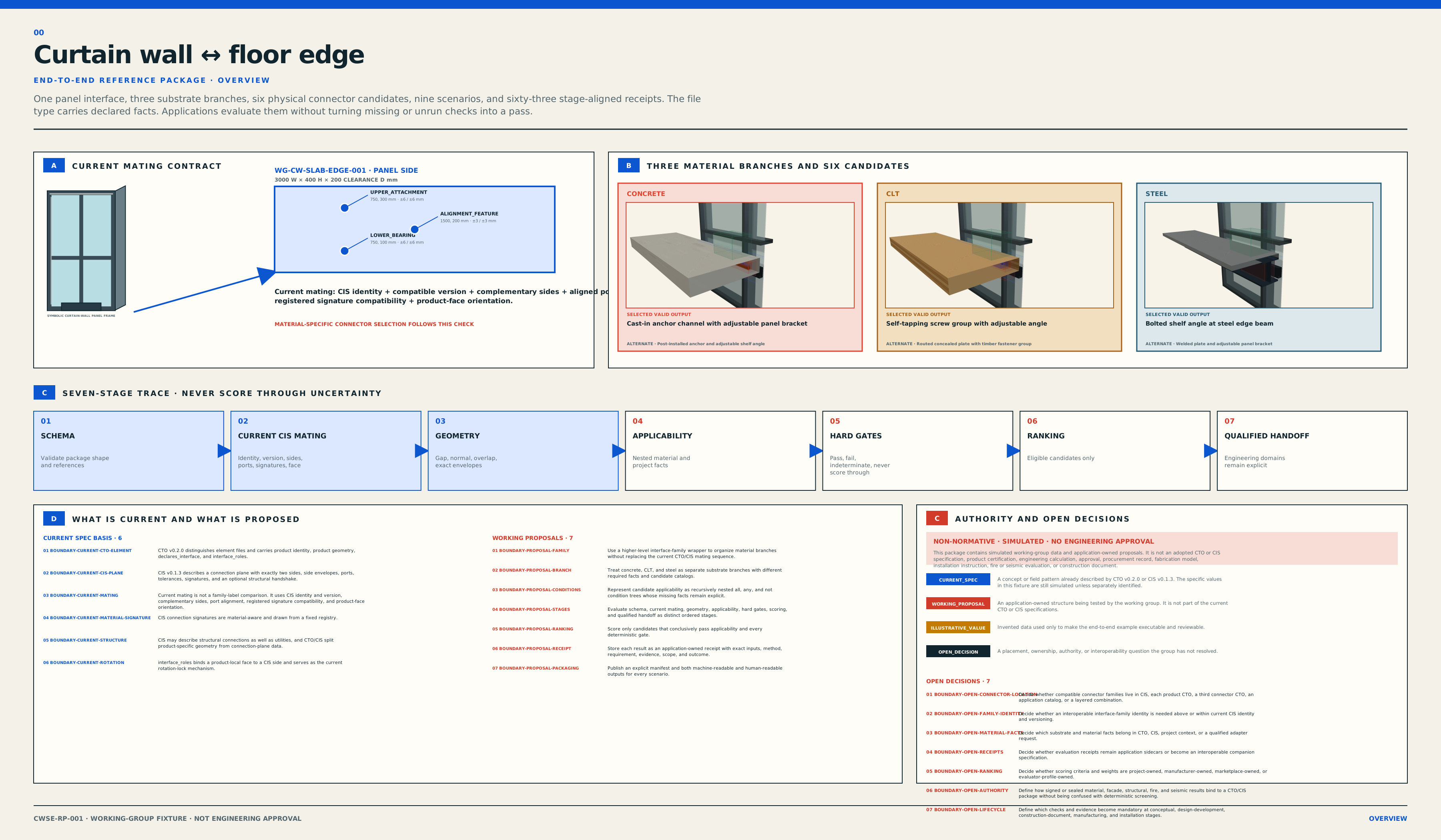
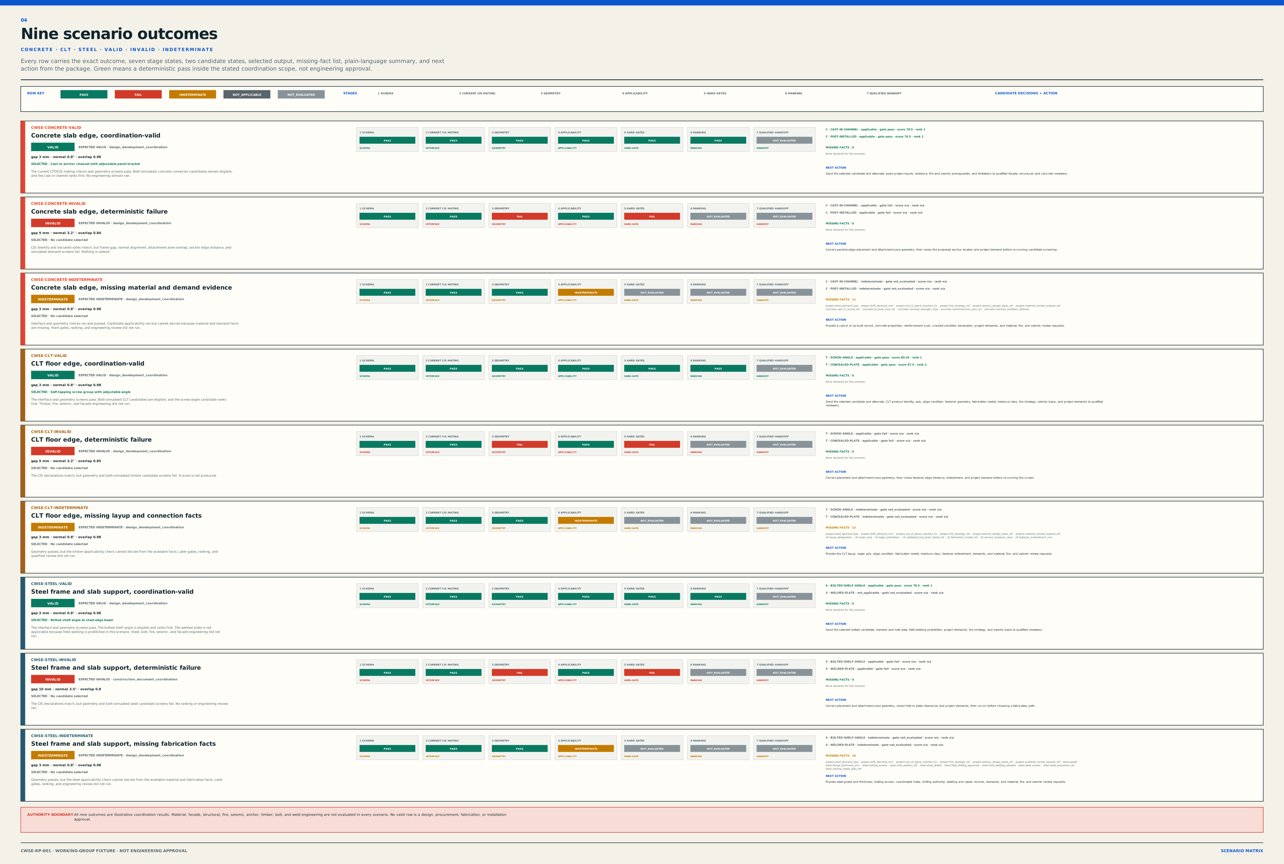
The package's illustrative unitized curtain-wall panel is traced from product declarations through current CIS mating behavior, a proposed classification layer, connector selection, scoped geometry checks, and auditable receipts.

01 / CASEOne unitized curtain-wall panel to a floor edge
03 / BRANCHESConcrete podium, CLT edge, steel edge or support
09 / SCENARIOSValid, invalid, and indeterminate per branch
01 / LIMITNo structural, fire, seismic, or facade approval
01

File and software boundary

Five layers, labeled by authority.

Current specification

A capability or rule stated in the vendored CTO v0.2.0 or CIS v0.1.3 drafts.

Proposed

A structure to test with the working group. It is not part of the current file type.

Illustrative

Simulated data used to make the proposal inspectable. Replace it with reviewed source data.

Open decision

A placement, governance, or scope question the working group still needs to resolve.

01 Current specification

CTO product declarations

Each product identifies itself, exposes reusable geometry and properties, and declares the CIS interface addressed by a product face.

  • Product identity and version
  • Externally relevant geometry
  • Declared interface reference
  • Face and rotation role
02 Current specification

CIS connection plane

The shared interface defines two sides, ports, positions, tolerances, connection signatures, and version compatibility.

  • Complementary sides
  • Port cluster geometry
  • Signature mating rules
  • Optional structural handshake
03 Working boundary

Project context

The assembly supplies the facts that change from one placement to another. Reusable products do not carry the demand of every possible building.

  • Instance transforms
  • Support and edge condition
  • Transformed gap, angle, and zone overlap
  • Evidence references and missing facts
04 Proposed

Selector and evaluators

Software resolves a proposed interface-family classification, filters connector families, applies hard gates, then scores eligible catalog options.

  • Rule and catalog versions
  • Hard exclusions before scoring
  • Missing-data detection
  • Material-specific adapters later
05 Application-owned

Evaluation receipts

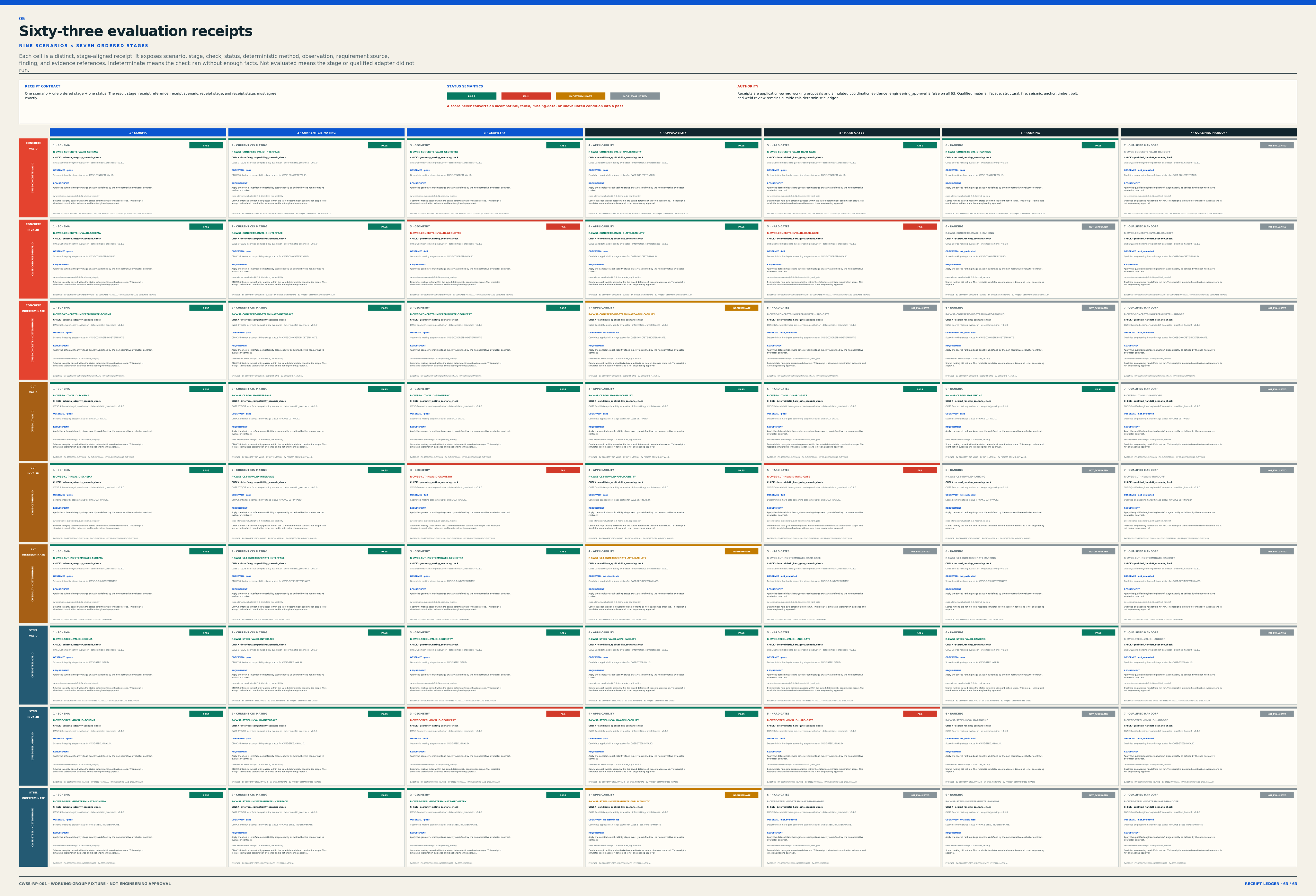
A receipt records what was checked, which inputs and rules were used, the finding, and what remained outside scope.

  • Pass, fail, indeterminate
  • Not evaluated kept distinct
  • Evidence and provenance
  • No hidden engineering claim
Geometry-first rule: a file can describe connection geometry and declared constraints. Software can test a scoped mating condition. Structural, fire, seismic, air, water, thermal, and durability conclusions require their own evidence, methods, and qualified review.
02

End-to-end trace

From context to a reviewable result.

The first two steps use current specification concepts. The remaining steps make the working proposal concrete without quietly rewriting CTO or CIS.

01 Boundary

Project context

Identify the panel system, floor edge, placement, access, and facts needed for this question.

context.connection_condition
02 CIS rule

CIS mating

Resolve the same CIS and compatible versions. Confirm opposite sides, aligned ports, tolerances, and compatible signatures.

cis.id + sides + ports + signatures
03 Proposed

Interface-family classification

Reference the proposed material-neutral interface wrapper so independent catalogs can describe solutions for the same connection intent.

project_context.interface_family_ref
04 Proposed

Eligible connector families

Use panel type, framing condition, substrate, edge condition, and role to narrow generic connector families.

selection.eligible_families[]
05 Proposed

Hard gates

Exclude options that fail required geometry, material applicability, evidence presence, or installation access.

evaluation.hard_gates[]
06 Proposed

Scoring

Rank only eligible options. Scores explain preferences and never override a failed or unknown hard gate.

selection.candidates[].score
07 Output

Selected geometric solution

Return the chosen connector ID, exact placement offset, two footprints, access status, protected-zone status, and evidence references.

evaluation_result.selected_geometric_solution
08 Sidecar

Receipts

Record each finding, missing input, evidence reference, rule version, and untested domain.

receipts[]
Normative here means current draft behavior, not final approval.

CIS v0.1.3 defines mating through the connection plane, sides, ports, tolerances, signatures, and compatibility. The sample CIS identifiers on this page are illustrative.

Interface family is deliberately not called normative.

The session proposed a reusable identity for a resolved connection condition. Its name, derivation, owner, registry, and version policy remain working-group decisions.

03

Data-derived technical atlas

See exactly what the package declares.

These drawings are generated from the versioned reference package. Exact envelopes and declared zones are separated from ghosted component anatomy so the page does not imply fabrication detail that the source files do not contain.

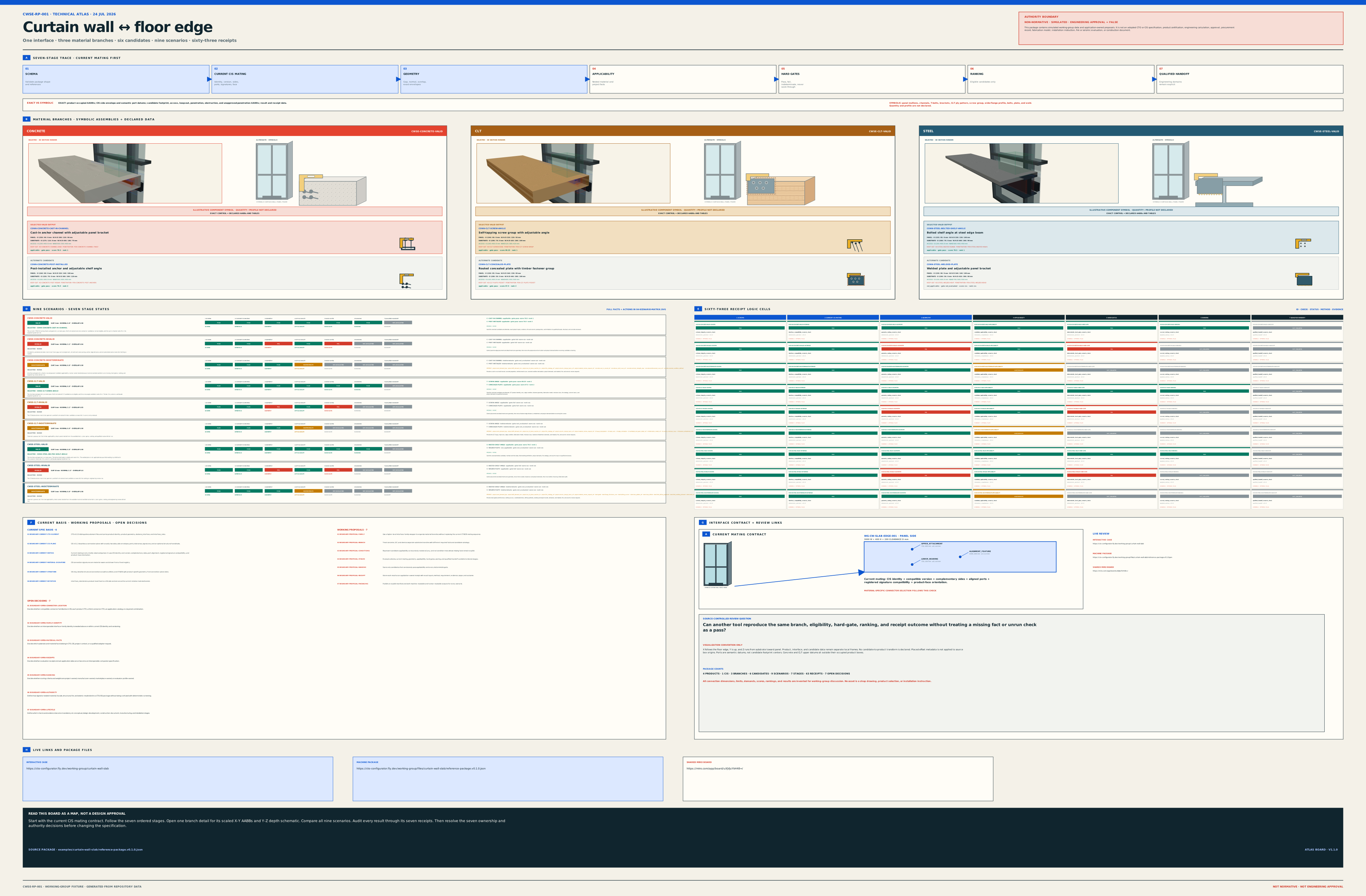
End-to-end CTO and CIS evaluation flow with project and product inputs followed by seven receipt-producing stages.
Input strip plus seven receipt stages Product and project context are inputs. Schema integrity, interface compatibility, geometry mating, applicability, hard gates, ranking, and qualified handoff are the ordered evaluation stages.
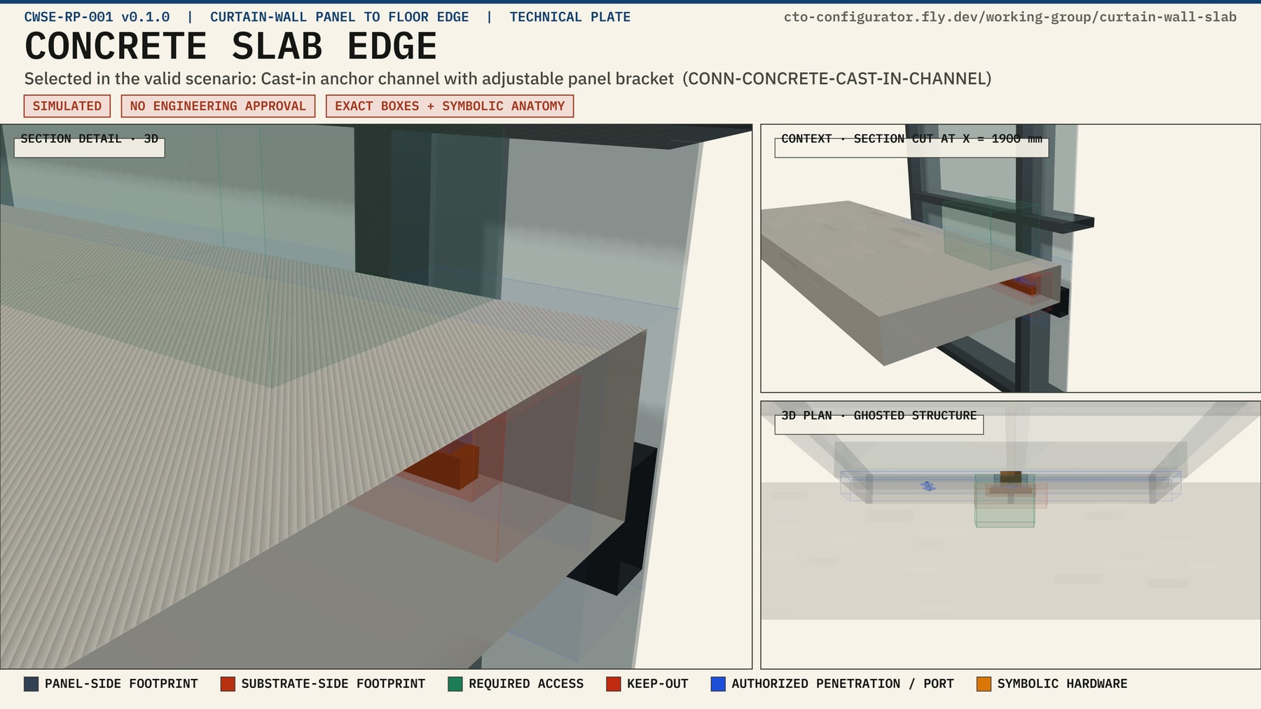
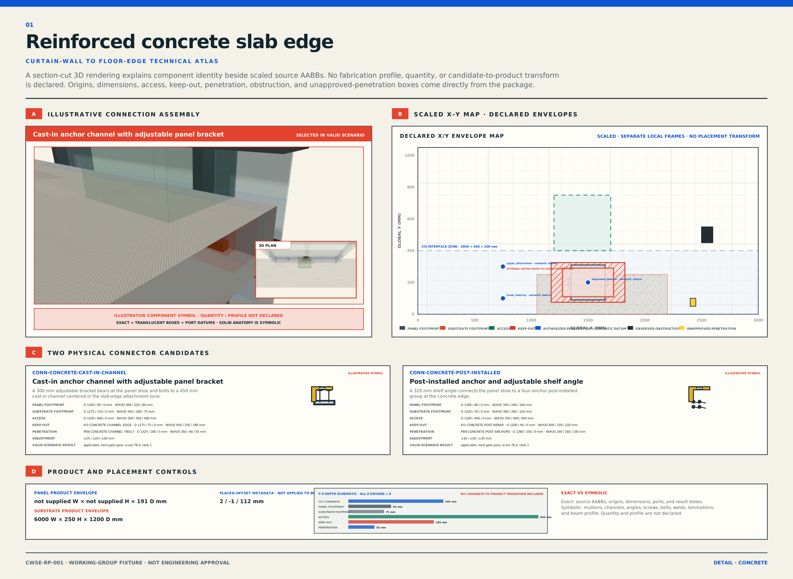
Three-dimensional section-cut rendering of the concrete slab edge with the cast-in channel candidate, exact declared zones, and the curtain-wall panel.
Concrete slab edge Section-cut 3D plate. Selected reference: cast-in channel and adjustable bracket. Exact declared boxes stay visibly distinct from symbolic hardware. Open the dimensioned 2D sheet.
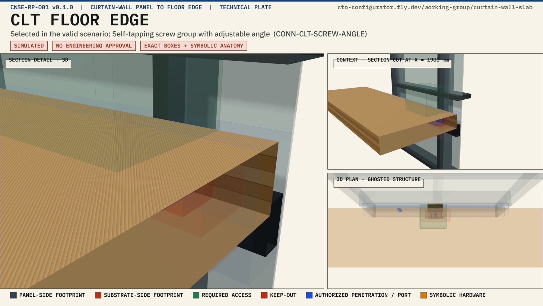
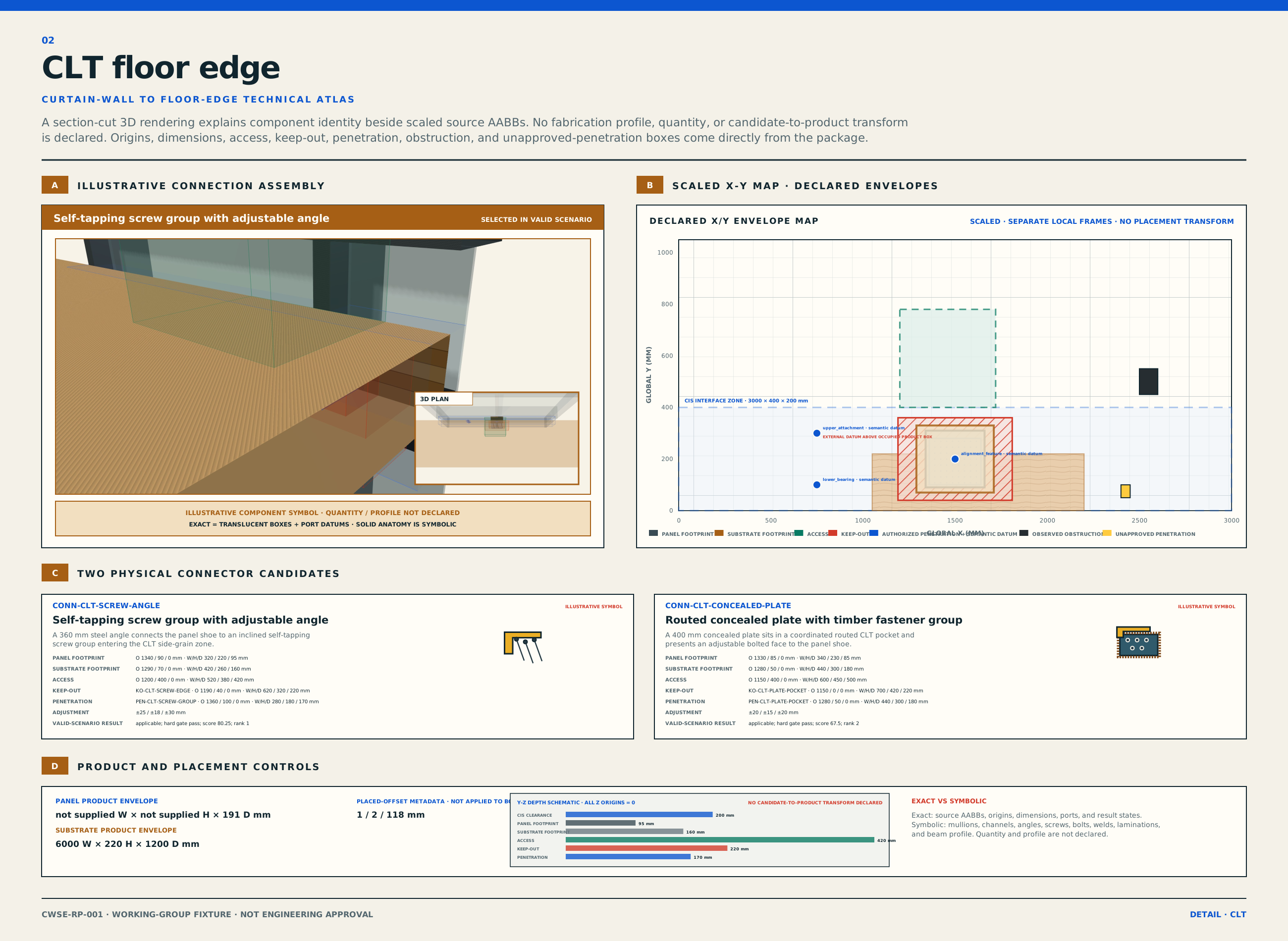
Three-dimensional section-cut rendering of the CLT floor edge with the inclined screw-group candidate, exact declared zones, and the curtain-wall panel.
CLT floor edge Section-cut 3D plate. Selected reference: self-drilling screw angle bracket. Screw pattern and timber layup remain symbolic because fabrication-level profiles are not declared. Open the dimensioned 2D sheet.
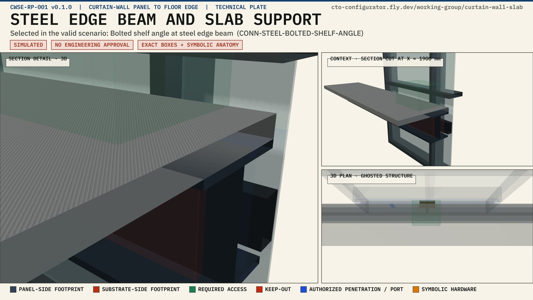
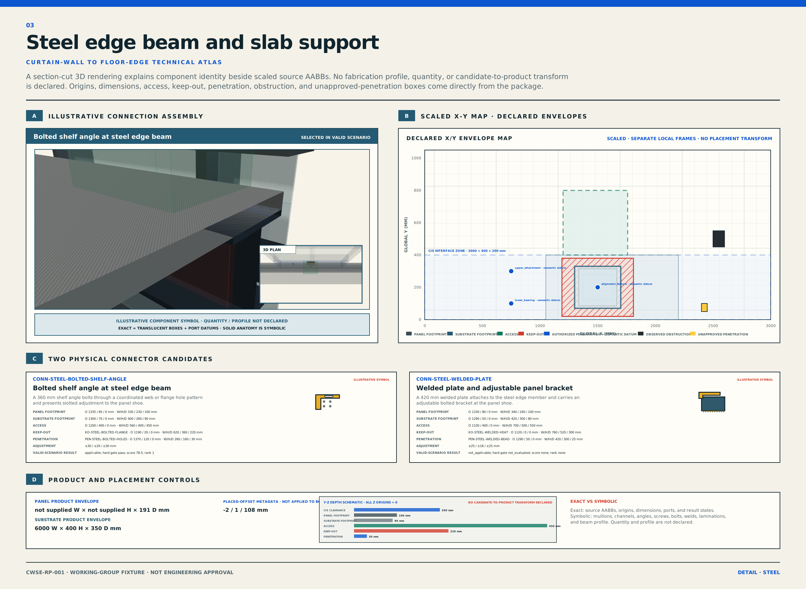
Three-dimensional section-cut rendering of the steel edge beam with the bolted shelf-angle candidate, exact declared zones, and the curtain-wall panel.
Steel frame and slab support Section-cut 3D plate. Selected reference: shop-drilled bolted clip. Member profile, hole pattern, bolt count, and fastener sizes are symbolic unless explicitly listed in the source data. Open the dimensioned 2D sheet.
Exact from package data

Occupied envelopes, candidate-side footprints, attachment zones, access zones, keep-out zones, penetration and obstruction observations, interface-local ports, and reported dimensions.

Symbolic until more geometry exists

Bracket profiles, fastener count and spacing, rebar, CLT ply build-up, steel section shape, panel internals, and a shared candidate-to-product placement transform.

03b

Interactive 3D condition viewer

Orbit the declared geometry.

The same package records rendered as a live 3D scene. Every translucent box is an exact declared value: candidate footprints, required access, keep-outs, authorized penetrations, the CIS envelope, and its port datums. Solid components are symbolic anatomy only.

Support system
Connector candidate
Explode

Loading the interactive scene.

Exact in this scene

Product occupied envelopes, candidate two-sided footprints, required access zones, keep-out zones, authorized penetration zones, the CIS side envelope, and interface-local port datums, all in declared millimeters.

Symbolic and composed

Mullions, glazing, laminations, beam profile, brackets, and fasteners are illustrative shapes. The assembled composition is a coordination view. The package declares no verified shared frame and no candidate-to-product transform.

04

Interactive case lab

Change the support. Change the outcome.

Choose a material branch and a disposition. The plain-language result and JSON are two views of the same simulated record.

Support system
Scenario disposition
CWSE-CONCRETE-VALID

Concrete slab edge, coordination-valid

Valid within geometry-first scope

The current CTO/CIS mating checks and geometry screens pass. Both simulated concrete connector candidates remain eligible, and the cast-in channel ranks first. No engineering domain ran.

Three-dimensional section-cut plate of the concrete slab edge with symbolic component anatomy and exact declared coordination zones.
Concrete slab edge technical atlas Exact source geometry is dimensioned in the XY and YZ maps. Ghosted component anatomy is illustrative. Open the drawing to inspect every label.
Ordered evaluation stages
Catalog candidates
Connector type / candidateApplicability and gatesScoreRankSelection
Selected geometric solution
Evaluation receipts
05

Variable and ownership map

Every input has a home and a status.

The first exercise should expose enough detail to test boundaries, while keeping proposed fields separate from current draft requirements.

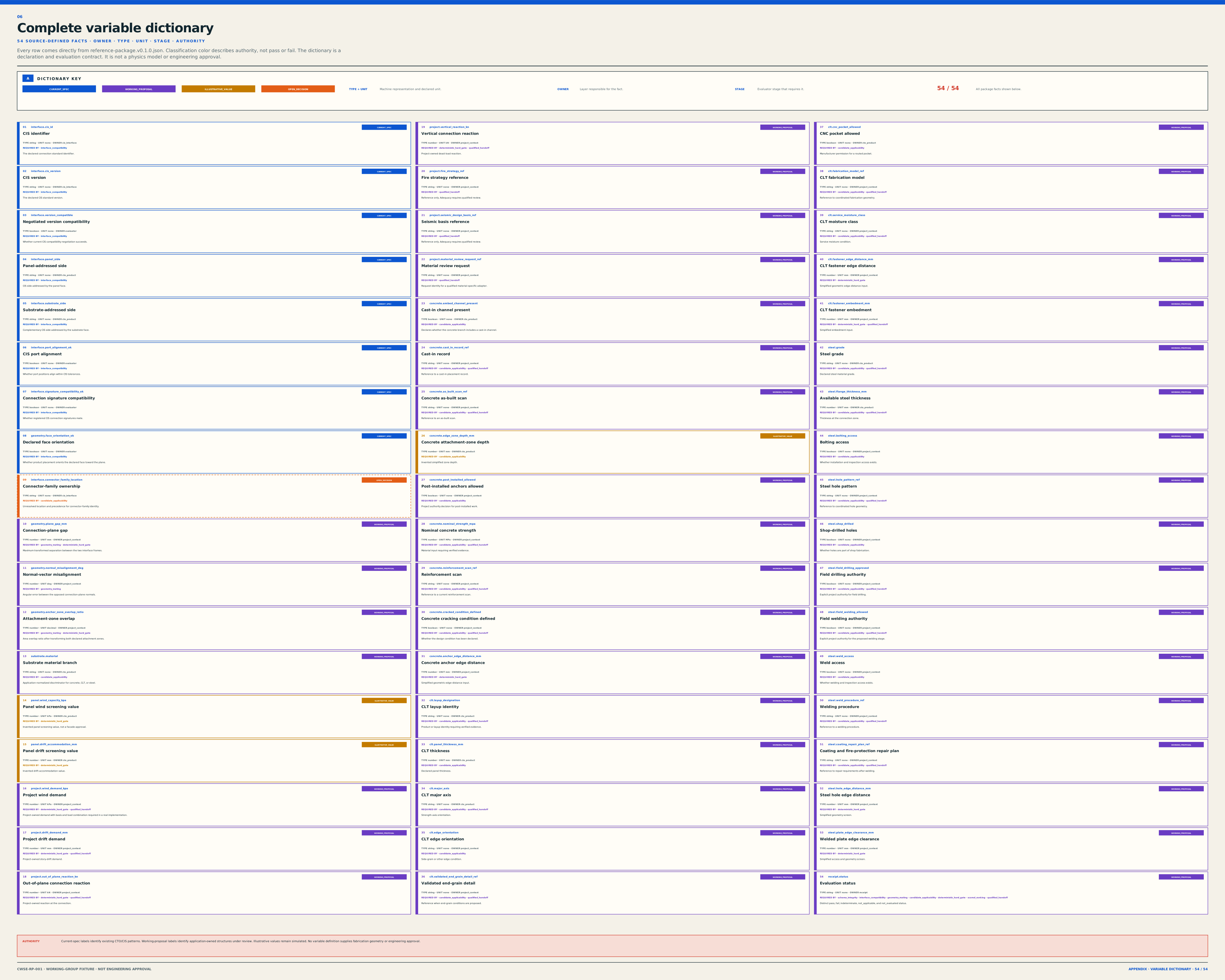
Variable Example Primary home Authority Why it matters
panel_system unitized_curtain_wall in the v0.1.0 panel CTO CTO product property Current CTO field pattern This package models one curtain-wall panel. Framed wall-panel systems require a separate future product and scenario branch.
frame_condition Not declared in the v0.1.0 package Candidate future CTO or project-context field Open decision Single-stud, double-stud, mullion, and perimeter-frame conditions must not be inferred from this package.
edge_condition concrete_slab_edge, clt_floor_edge, steel_frame_slab_support Support CTO subcategory plus scenario branch Materialized values Selects one of the package's three substrate branches and its two candidate records.
location_condition Not represented in v0.1.0 Candidate future project-context field Open decision Exterior edge, interior line, opening edge, and return conditions need an explicit future field.
connection_role panel_sidesubstrate_side; product-local back face ↔ front face CTO interface role and CIS side Current concept Confirms complementary orientation at the connection plane.
substrate.material reinforced_concrete, clt, structural_steel Support product declaration Typed value Selects the material-specific applicability branch and evidence requirements.
cis_ref + side + port Illustrative CIS instance, side A/B, structural port cluster CTO reference and CIS Current specification Lets software validate shared standard, side complementarity, port geometry, tolerance, and signature.
geometry.plane_gap_mm + normal_misalignment_deg + anchor_zone_overlap_ratio Valid records use 3 mm, 0.8 deg, and 0.98 Project-context facts evaluated at geometry_mating Materialized values These exact values drive the package's geometry-stage status and interface receipt.
geometry_solution.required_access_zone_mm + access_zone_clear Candidate requirement plus selected-solution boolean Connector catalog and evaluation result Materialized values The page reports the exact selected footprint, offset, access status, and protected-zone status.
interface_family_ref WG-CW-SLAB-EDGE-001 for all nine scenarios Working project-context reference to the material-neutral CIS projection Not normative The single working wrapper does not replace current CIS mating and does not choose a material-specific connector.
connector_type Adjustable bracket, plate, strap, or clip Connector catalog Catalog layer First filters the type, then selects an eligible product inside that type.
evidence[] Geometry declaration, supplier data, test report reference, qualified calculation reference Declaration or project context by source Open placement Prevents a number or rule from losing its authority, revision, scope, or provenance.
structural / fire / seismic not_evaluated in the geometry-first phase Future domain evaluator and receipt Explicit limitation Keeps an unperformed analysis from being mistaken for a pass or an information gap.

Outcome vocabulary

Pass / valid scope

The scoped rule ran and passed.

All required inputs for that rule were present. This does not imply that another discipline or the complete assembly is approved.

Fail / invalid

The scoped rule ran and failed.

A known requirement was not satisfied. Scoring cannot rescue a candidate that fails a hard gate.

Indeterminate

The rule was in scope, but a required fact was missing.

The correct response is to request the missing input. Missing information is not zero and is not a passing result.

Not evaluated

The rule did not run in this phase.

Structural, fire, seismic, air, water, and other engineering checks stay here until an identified method and qualified review are supplied.

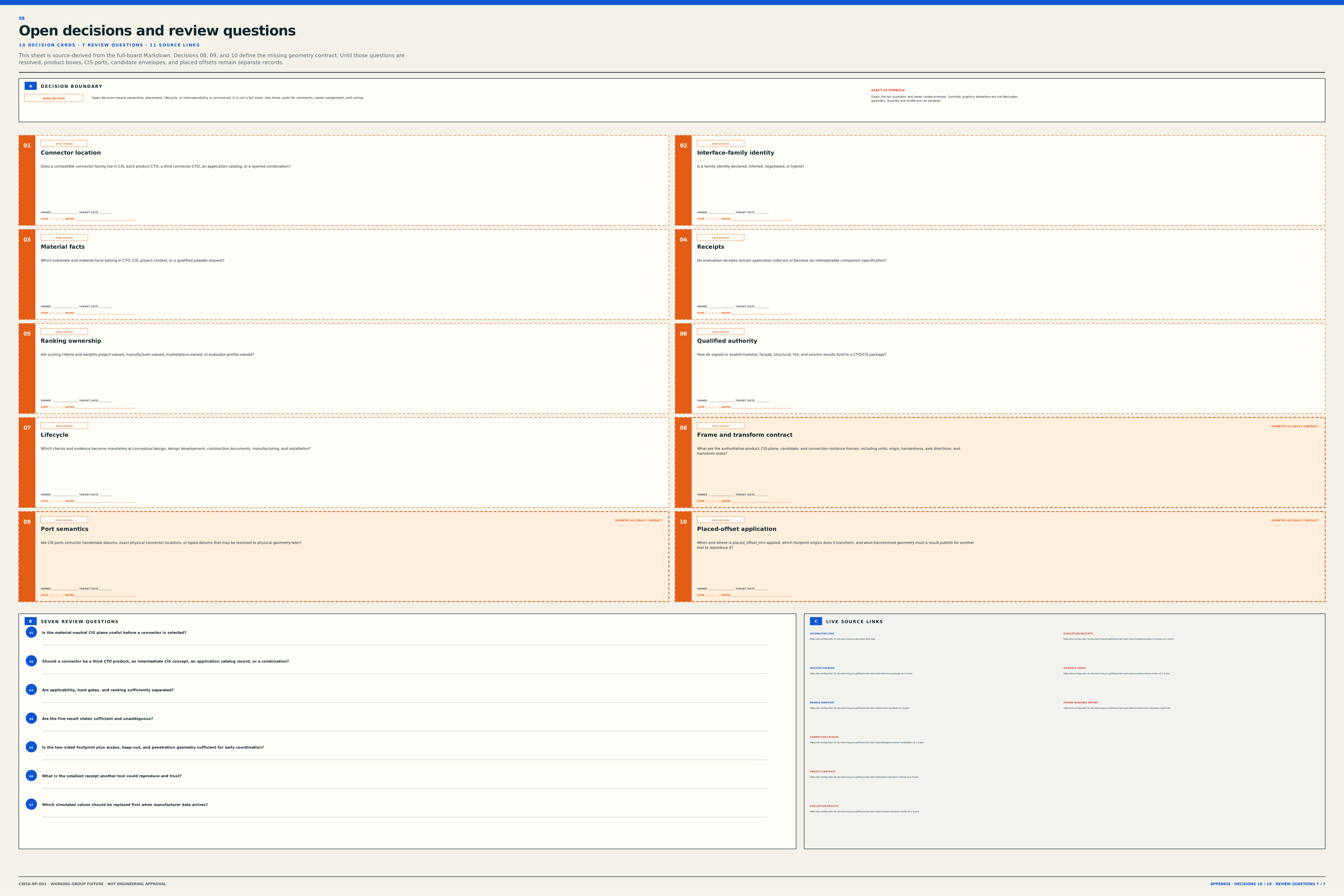
Who creates the interface-family identity?

Decide whether it is selected, inferred, negotiated, or registered, and who controls its identifier and version.

Where do evidence references live?

Decide which references belong in CTO, CIS, the project context, a catalog record, or a receipt.

What is a hard gate?

Agree which conditions always exclude a connector and how an unknown required condition affects eligibility.

How do private catalogs participate?

Define how a manufacturer can implement a shared condition without exposing internal logic or confidential product data.

06

Machine and human package

Inspect the same idea at four levels.

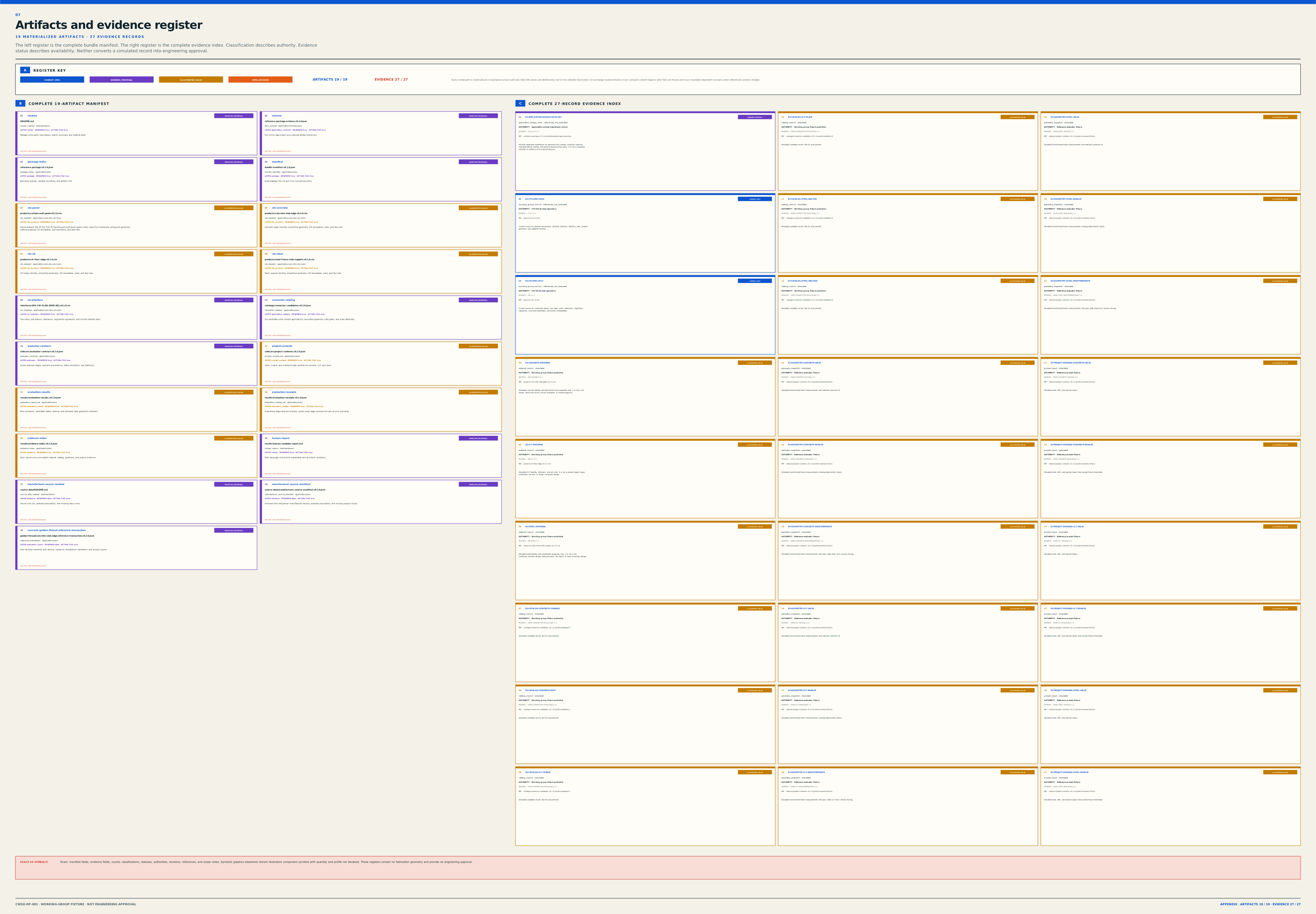
The page is working-example revision v0.3. The materialized machine bundle begins at v0.1.0. Both lab views project the same embedded source records from that bundle, and the exact versioned files remain available above.

Engineering limitation

All connector dimensions, tolerances, edge distances, capacities, performance references, score weights, and scenario values in this working example are illustrative unless a source is explicitly identified. They are not structural, facade, fire, seismic, air, water, thermal, acoustic, code, fabrication, or installation approval. Qualified reviewers must confirm the governing criteria and evidence.